Ohm's Law - A Little Background
Ohm's law: states that the current (I) through a conductor between two points is directly proportional to the voltage (E) across the two points, where I is the current through the conductor in units of amperes, V is the voltage measured across the conductor in units of volts, and R is the resistance of the conductor in units of ohms. Ohm's law also states that the 'R' in this relation is constant, independent of the current.
Resistors: are components that tend to slow down or impede the flow of electricity. The values of resistors are fixed, except for variable resistors. There are numerous types with the most common called carbon resistors. In electrical diagrams or schematics they are represented by a zig-zag picture and the letter 'R' or the Greek symbol "Ω". To measure the resistance of a component you use an ohm meter and measure across the component. This is the resistance or push back to the current flow.
Voltage: is measured across the component you wish to measure. It is the difference in the charge or electrons between two points.
Current: is measured in series with the component. It is the rate at which the charge or voltage is flowing.
Reactive Circuits: include components such as inductors, capacitors or transmissions lines and are generally associated with alternating current or AC circuits. Ohm's law here does not directly apply to this type of circuit. There are no resistors in it. The ac equivalent of resistance is called impedance and is represented by the letter or symbol 'Z.'
In circuit analysis, three equivalent expressions of Ohm's law are used interchangeably:
- V = I * R // Voltage = Current * Resistance
- R = V / I // Resistance = Voltage / Current
- I = V / R // Current = Voltage / Resistance
Each of the above equations can be retrieved from the triangle on the right. Cover the one you need and the two left standing are your answer.
The tool for measuring volts in an electric circuit is called a voltmeter. An ohmmeter is used for measuring resistance. A multimeter can measure several functions including voltage, current, resistance, and temperature.
Resistors In Series: When resistors are connected end-to-end in a circuit (like shown in the picture below) they are said to be in "series." In order to find the total resistance of resistors in series you just add up the value of each resistor. In the example below the total resistance would be R1 + R2.

This is another example of resistors in series. The total value of the resistance across the voltage V is R1 + R2 + R3 + R4 + R5.
Parallel Resistance Circuit:Parallel resistors are resistors that are connected across from each other in an electric circuit. See the picture below. In this picture R1, R2, and R3 are all connected in parallel to each other.
When we calculated the series resistance, we totaled the resistance of each resistor to get the value. This makes sense because the current of a voltage across the resistors will travel evenly across each resistor. When the resistors are in parallel this is not the case. Some of the current will travel through R1, some through R2, and some through R3. Each resistor provides an additional path for the current to travel.
In order to calculate the total resistance "R" across the voltage V we use the following formula:

1/R = ¼ + 1/5 + 1/20
1/R = 5/20 + 4/20 + 1/20
1/R = 10/20 = ½>br>
R = 2 Ohms
You can see that the reciprocal of the total resistance is the sum of the reciprocal of each resistance in parallel.
The total resistance is less than the smallest resistor value in parallel circuit. This will always be the case.
Series Parallel Circuits: The idea for solving these types of circuits is to break down smaller parts of the circuit into series and parallel sections. First do any sections that have only series resistors. Then replace those with the equivalent resistance. Next solve the parallel sections. Now replace those with equivalent resistors. Continue through these steps until you reach the solution.
Below is a simple series parallel circuit:
First we will total the two series resistors on the right (1 + 5 = 6) and on the left (3 + 7 = 10). Now we have reduced the circuit.
We see on the right that the total resistance 6 and the resistor 12 are now in parallel. We can solve for these parallel resistors to get the equivalent resistance of 4.
1/R = 1/6 + 1/12
1/R = 2/12 + 1/12
1/R = 3/12 = ¼
R = 4
The new circuit diagram is shown below:
From this circuit we solve for the series resistors 4 and 11 to get 4 + 11 = 15. Now we have two parallel resistors, 15 and 10.
The equivalent resistance across V is 6 ohms.
Simple Electrical Circuit and Ohm's Law Wheel and Triangle


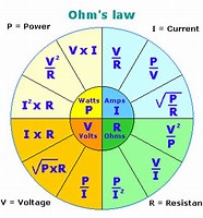
Formula Wheel With PIE: If you look at the wheel above you will see it's divided into four sections. The four are Amps (I) for current, Voltage (E) for volts, Ohms (R) for resistance and a new one, Watts (P) for power.
It looks complicated but using it is really simple.
- Know what you're trying to solve for, example: voltage or E.
- What values you already have.
- Find the section that all your values match.
- Solve the problem.
Short-Cut Formulas
For resistors in parallel: If all the resistors are of equal value count the resistors and divide that into the value of one resistor. Example: you have ten resistors that are all 100 ohms. Dividing 100 by 10 gives you 10 ohms for Total Resistance.
Another way of saying the above is: If the two resistances or impedances in parallel are equal and of the same value, then the total or equivalent resistance, RT is equal to half the value of one resistor. That is equal to R/2 and for three equal resistors in parallel, R/3, etc. Note that the equivalent resistance is always less than the smallest resistor in the parallel network so the total resistance, RT will always decrease as additional parallel resistors are added.
A Pair Of Resistors - if you have 2 resistors in parallel the the following applies:
- Multiply the resistances. Example: Two resistors in parallel, 100 and 200 ohms. 100 x 200 = 20,000
- Add the resistances. Example: 100 + 200 = 300
- Divide the result in Step 1 by the result in Step 2. This gives you the total resistance. Example: 20,000 / 300 = 66.7 ohms.
- This only works for two (2) resistors!
Other LAWS or Rules You Might Find Interesting
Coulomb's Law: The magnitude of the electrostatic force of attraction or repulsion between two point charges is directly proportional to the product of the magnitudes of charges and inversely proportional to the square of the distance between them. The force is along the straight line joining them. If the two charges have the same sign, the electrostatic force between them is repulsive; if they have different signs, the force between them is attractive.
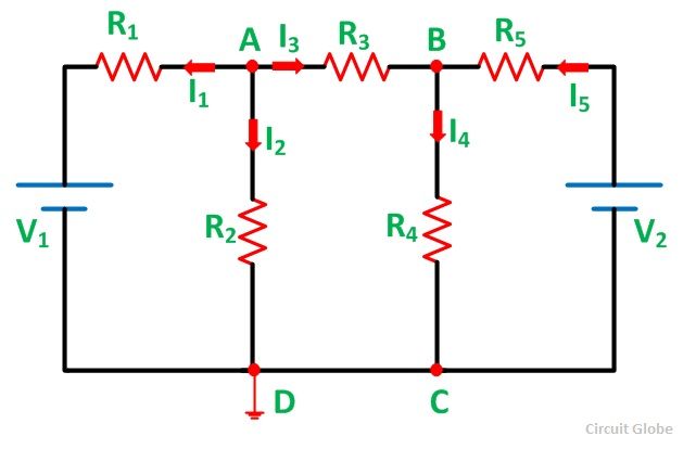
Kirchhoff's Laws (Voltage and Current):
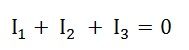
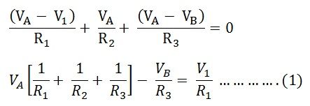
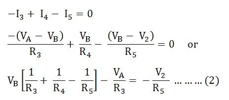
Current Law: The algebraic sum of current into any junction is zero.
The sum of current into a junction equals the sum of current out of the junction.
Since current is the flow of electrons through a conductor, it cannot build up at a junction, meaning
that current is conserved: What goes in must come out. Picture a well-known example of a junction: a
junction box. These boxes are installed on most houses. They are the boxes that contain the wiring
through which all electricity in the home must flow.
If you had a junction of four conductors (wires), the currents v2 and v3 are flowing into the junction,
while v1 and v4 flow out of it. In this example, Kirchhoff's Junction Rule yields the following equation:
v2 + v3 = v1 + v4
Voltage Law: Kirchhoff's Voltage Law describes the distribution of electrical voltage within a loop, or closed conducting path, of an electrical circuit. Kirchhoff's Voltage Law states that:
The algebraic sum of the voltage (potential) differences in any loop must equal zero.
The voltage differences include those associated with electromagnetic fields (EMFs) and resistive elements, such as resistors, power sources (batteries, for example) or devices—lamps, televisions, and blenders—plugged into the circuit. Picture this as the voltage rising and falling as you proceed around any of the individual loops in the circuit.
Kirchhoff's Voltage Law comes about because the electrostatic field within an electric circuit is a conservative force field. The voltage represents the electrical energy in the system, so think of it as a specific case of conservation of energy. As you go around a loop, when you arrive at the starting point has the same potential as it did when you began, so any increases and decreases along the loop have to cancel out for a total change of zero. If they didn't, then the potential at the start/end point would have two different values.
When crossing a resistor, the voltage change is determined by the formula:
I*R where I is the value of the current and R is the resistance of the resistor. Crossing in the same
direction as the current means the voltage goes down, so its value is negative. When crossing a
resistor in the direction opposite the current, the voltage value is positive, so it is increasing.
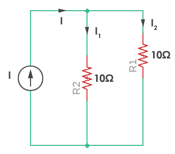
Voltage and Current Divider Circuits:
The Basics: Voltage Divider and Current Divider are the most common rules applied in practical electronics.
As you know, there are two types of combinations in a circuit, they are series and parallel connections. Parallel
circuits are also known as current divider circuits because, in these circuits, the current is divided through each
resistor. Whereas, series circuits are known as voltage divider circuits because here voltage is divided across
all the resistors. Voltage division rule and current division rule are necessary to understand voltage and the
current flowing through each resistor. These division rules are used in most common electronic devices.
Voltage Divider:
As we got to know that, a series circuit is known as a voltage divider circuit. It is a circuit which divides the
voltage into small parts. So with a power source and two resistors, we can make an easy voltage divider circuit.
Here we need to connect two resistors in series combination and then apply a voltage source across the series
circuit.
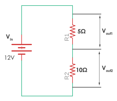
In this case, resistor R1 = 5 ohms and resistor R2 = 10 ohms. The voltages Vout1 and Vout2 are divided across the resistors R1 and R2. They can be calculated by a simple voltage dividing equation.
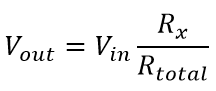
Where Rx is the resistor across which we need to find the voltage and Rtotal is the total resistance (R1+R2) in the circuit. It can be simply calculated by adding all of them as they are connected in series. Thus in the given circuit, the values of the voltage across each resistor are
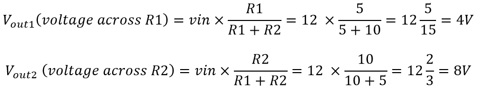
So you wind up with 4 volts across R1 and 8 volts across R2, hence a simple voltage divider.